

![]()

BOEY
Nagi Chung Malcolm
01200922
Contents
- Learning PC WORX
3 at Fachhochschule Lippe und Höxter
- The first task at
Phoenix Contact: Test rack INTERBUS Field multiplexer
- The second task:
Analysing the errors in current transmission
- The next pending
task: Test rack for Remote Software
- My living
experience in Lemgo, Germany
- Quick Start
- Quick Start for
multiple remote stations
Learning
PC WORX 3 at Fachhochschule Lippe und Höxter
This part of the attachment is to learn a
new programming package, PC WORX 3. This software is authored by Phoenix
Contact, the company I am working in now. Prof. Meier, our supervisor in
the Fachhochschule, (FH) assigned Michael Fuhs, a student there, to
guide us in our learning. I started off by fixing up some InterBus hardware
from Phoenix Contact. I was introduced to two ranges: ST and Inline. They are
different physically but can be programmed to work together using PC WORX 3.
I started off by learning to programme
using Structured Text. This language is quite similar to VHDL. I learnt that in
Microchip Technology, a second-year module. The programme that I typed will be
compiled by PC WORX 3 and be run on the InterBus hardware. This hardware can
consist of many devices. The devices I learnt to use were inputs and outputs,
both in digital and analogue electrical signals. These devices are assigned to
external variables in the programme. Some devices, for example the analogue
input, also requires some configuration to choose the mode of operation,
whether inputting current or voltage, whether using 12- or 15-bit numbers or
whether reading only positive or bipolar (positive and negative) values.
We accomplished some tasks set by Michael
Fuhs, like running a binary counter at the digital outputs and drawing a
voltage ramp from the analogue voltage output.
On 3 June 2003 I visited Phoenix Contact
with my partner, Michael Fuhs and Prof. Meier. We were given a
presentation by Mr Christopher Hadi about the company’s history and by
Mr Joachim Pucker about our tasks to be accomplished during out
attachment in Phoenix Contact. In the presentation I was confronted with new
terms like dedicated line modem, RS232, RS485 and multiplexer. After the visit,
I returned to the FH and started to read up and ask around about the terms.
RS232 and RS485 are serial communications. A dedicated line modem is just like
any modem, but it can be configured to work on private lines. The private line
can consist of a pair of wires only. Since there isn’t a dial tone and a ring
signal as found in normal telephone systems, the modems are configured to
proceed with the handshake as soon as they are turned on. I still haven’t
understood what a multiplexer was when I left the FH on 1 July 2003.
The first task at Phoenix Contact: Test rack INTERBUS Field multiplexer
The description as given from my
supervisor, Mr Joachim Pucker:
Digital
and similar in and output signals must be transmitted often across large
distances to
central
controls and in reverse. Solutions with multi-wire copper cables are however
very complex and expensive - both which the cables themselves, and their
shifting concern. The interbus field multiplexer reduces exactly these costs
drastically. It transfers the signals only over one core cable.
Up
to 512 input/output data can be transferred from point to point over a distance
of up to 12 km (dependent on the used type of cable and the EMC site
conditions). Optionally the
transmission can be made also by fibre-optic cables. Normally usable cables
already exist. A large selection of one and more-channel INTERBUS Inline In-
/output modules can be plugged in subsequently at the field multiplexers. So it
can be used flexibly and at small wiring expenditure everywhere, where
economically larger distances are to be bridged. A configuration software is
not necessary. The INTERBUS field multiplexer transmits data over a copper line
up to a distance of 12 km. In some applications it can occur that this conduit
length is not sufficient and further distances must be bridged. If no own
dedicated line is present at the customer partly a line must be rented by the
Telecom. In order to transmit data over lines of the Telecom it is necessary to
use a modem connection.
The
objective of this task is to evaluate the feasibility by using an existing dedicated
line connection over 12km and the connection also over a Telecom dedicated
line.
Using
modules:
- Field multiplexer
- RS232/RS485 converter
- PxC analogue/dedicated line modem
 Due to the fact that the field multiplexer uses physical data
transmission of RS485 and the at PxC available modem provides a RS232-Interface
it is necessary to use a RS232/RS485 converter here.
Due to the fact that the field multiplexer uses physical data
transmission of RS485 and the at PxC available modem provides a RS232-Interface
it is necessary to use a RS232/RS485 converter here.
 The equipment used:
1.
 Two “IB IL 24 MUX MA”
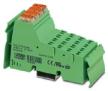
2.
![]() Two “PSM-ME-RS232/RS485-P”
Two “PSM-ME-RS232/RS485-P”
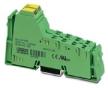
3.

![]() Two “IB IL 24 DI 2”
Two “IB IL 24 DI 2”
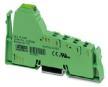
4.
![]() Two “IB IL 24 DO 2-2A”
Two “IB IL 24 DO 2-2A”
5.
24
Volts DC power supply
6.
Four
push-button switches with 24-Volt built-in light bulb
The picture of the layout:
Censored
The outcome
I connected the hardware as described. It
wouldn’t work as expected. I suspected that the modems weren’t functioning
properly. I cleared this doubt when I connected the modems to the serial ports
of 2 computers. Running the terminal emulator HyperTerminal, the modems were
working because every character sent was received correctly. My next suspicion
was that the data format used wasn’t a standard one. This is because the TxD
light of the converter at the transmitting side was blinking and the RxD light
of the converter at receiving side was also blinking at the same time. This
shows that the data is transmitted. However the multiplexers wouldn’t respond.
The only working model was made when the converters were directly connected
together using a RS-232 cross cable. We report this problems to our supervisor,
Mr Pucker. He told us to take a pause on this task and proceed to the
next task.
The second task: Analysing the
errors in current transmission
The
equipment used:
1.
All
the same as the previous task
2.
 One “IB IL AI 2/SF”
3.
![]() One “IB IL AO 1/SF”
One “IB IL AO 1/SF”
4.
Two
digital Amp meters
Mr Pucker
asked me to transmit current signals and monitor the error. He needed this
information so that the customers who want to transmit currents can take note
of the possible inaccuracy. I used the same multiplexer set-up as the previous
project, except that an Analogue Input device was inserted in one side and an
Analogue Output device was inserted on the other side. I used another Analogue
Output connected to a controller to generate the current signal. I transmitted
20 current values randomly ranging from 0 to 20 mA. I recorded the current sent
and the current received. I plotted these differences onto a line graph. The
conclusion is that current values from 0 to 4 mA is not accurately sent.
Current from 4 to 20 mA are accurately sent with error percentage values below
5%. The graph attached shows the results of this test.
The next pending task: Test
rack for Remote Software
The description as given from my
supervisor, Mr Joachim Pucker, translated from German to English by
Teddy Low and Malcolm Boey:
It is possible to transfer data over long
distances with components of PxC's IB field multiplexers. The functions of this
equipment are often over the requirements of the remote-control technology. For
example, when control functions are needed to be integrated in the Remote
station or when a parallel wiring between the MUX centre and the SPS doesn't
want to be used. A PCWORX software-library was developed for these requirements
of work-technical applications. This library consists of two parts. The first
part was made possible by dedicated line connections over different medium like
RS485, dedicated line modem or radio modems so that several remote Field
CONTROLLERS by PxC can be interlaced over far distances, where bypassing using
a cross-link over a field bus or Ethernet is not possible.
The goals of this task are to test the
different scenarios for the beta software before its commercial release and if
necessary one documentation of the tests is to be made so that the software can
be modified. The further task is to provide a Quickstart for the future customers
which require a quick start in their enterprises.
 Please consider, when
encountered with difficulties in the start-up, it is necessary that you
document everything concerning your tests. This way, assistance can be provided
with the Quickstart. Are further diagnostic possibilities required or can the
users get along with the given diagnosis?
Please consider, when
encountered with difficulties in the start-up, it is necessary that you
document everything concerning your tests. This way, assistance can be provided
with the Quickstart. Are further diagnostic possibilities required or can the
users get along with the given diagnosis?
The equipment used:
1.
![]() Two “ILC 200 IB”
Two “ILC 200 IB”
2.
 Two
“IB IL RS 485/422”
Two
“IB IL RS 485/422”
3.
![]() One “IB IL 24 DI 16”
One “IB IL 24 DI 16”
4.
![]()
 One
“IB IL 24 DO 16”
One
“IB IL 24 DO 16”
5.
24
Volts DC power supply
6.
A
row of switches to simulate the logical conditions at the Digital Inputs
The picture of the layout:
Censored
The outcome
I constructed a test rack with only 2
stations, a master and a remote station. They are connected together through
the RS-485 protocol only using a twisted-pair cable. I configured them using PC
WORX 2 and ran the programme. The signals transmitted were correct but there
were delays. I decided to focus on measuring the delays. An extra programme
block was run and it measures the delays in terms of seconds from the switching
of the input to the reception of the output signal. The output is fed back from
the output at the remote station to the input at the master. I also tested for
delays occurring at different baud rates of the RS-485. The general conclusion
is that the slower the baud rate the longer the delay. After testing a
2-station set up, I constructed more remote stations, connected them together
and continued to test for delays happening on 3-, 4- and 5-station set ups. I
also authored 2 “Quick Start Guides” which are meant for customers who want to
start running this remote control set up quickly. These documents are attached
at the end of this report.
My living experience in Lemgo,
Germany
After being in Germany for approximately
3 months, I’ve experienced a totally different lifestyle compared to
Singapore’s. Not only having language differences, the cultural, environment
and working attitudes are different as well. For a start daily living is
different. People here start work early. Students start lessons at 07:45 and
usually nobody is late. At my present workplace, the office is usually buzzing
with activity from 08:15. Because I depend on others for transport from Lemgo
to Blomberg (the location of Phoenix contact), I also follow their time. I usually
step into the office before 07:15. Work ending also depends on the transport
arrangements. From Monday to Thursday, I am usually off by 15:30. On Fridays,
some people take a half-day off and on those days, I am off by 13:00. Nobody
works on Saturdays. This is different as compared to Singapore where work is
from 08:30 to 17:30.
Without any parent or guardian by my side
here in Lemgo, I depend on myself for survival. I’ve learnt to appreciate my
mother’s skill of cooking and washing. Here I do them myself. I go shopping and
walk back with all the heavy produce carried by my hands. I always cook weekday
dinners with my partner but on the weekends I am really on my own. I have
picked up some cooking skills while I am here and this skills will be helpful for
me when I live alone in the future. I have also learnt to wash my own clothes.
Actually, I just have to put the clothes into the washing machine, pour in some
detergents and softener and start the washing programme. After the programme is
executed, I have to take out the clothes and dry them.
Mixing around with Lemgo was not as easy
as it goes. Till now I think I only have less than 10 contacts with students of
the FH. This may be due to the fact that I live in a private room with my own
kitchen and bathroom, so I need not walk out of my room often. When I was
working in the FH, I was in a lab with only my partner. I wasn’t in an
environment with other German students. In Phoenix Contact, I work in a big
office with half walls separating the desks. This way, I made contacts with
other employees easily, but not students of the FH.
I have regular contact with other NP
students doing their attachment in Germany. The other pair from MIDAC are in
Mannheim and my partner and I plan to pay them a visit soon. The pair from
Mechatronic Engineering are in Bochum. Their project for now is to help up in
the construction of a solar-powered car that will race in the World Solar
Challenge. As it is convenient for me to travel to Bochum from Lemgo, I visit
them frequently and take them out for some trips that involve travelling to
interesting places in Germany and Europe.
I also meet up with some German students
who have been to NP for their attachment. One of them is Stefan Schrader who
was attached to Mr Chua’s DAB lab. He brought us out to Hameln and Bodenwerder
and he also kindly invited us to his house for coffee and cakes.
Finally with so many weekends at my
disposal, I’ve visited many places. Hameln (the piped piper town), Berlin (the
capital of Germany), Hamburg, Hannover, Bielefeld, Bochum, Düsseldorf,
MovieWorld, Köln (Cologne), London, Frankfurt, the Rhein River, Aachen,
Brussels, Brevörde, Bodenwerder. I’ve many other plans for the remaining
weekends that I have left in Germany.
Quickstart Guide
Connecting the hardware
- To set up a point-to-point connection, please buy 2 sets of: ILC 200 IB, IB IL RS 485/422 and the required input and output modules.
- Connect one ILC 200 IB, IB IL RS 485/422 and the necessary inputs and outputs together. This will be the Central station.
- Connect another ILC 200 IB,IB IL RS 485/422 and the complementing inputs and outputs together. This will be the one and only decentralised station.
- Connect a twisted-pair wire to the RS 485 ports as shown. Then connect the necessary power supplies and the input and output devices.
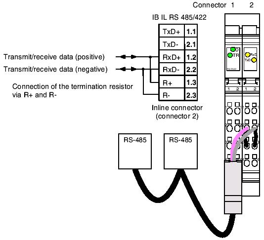
Source: IB IL RS 485/422, Data Sheet 6199B
Using PC WORX 2 to configure the stations
Please configure the Central station in this manner:
- Open “Zstand” under “Logical POUs”
- Open “Server” and configure the function block as shown: (Ignore those parameters that are not mentioned)
|
Parameter |
|
Setting |
|
IN_LX_FreigabeBaustein |
|
TRUE |
|
IN_LW_Prozessdatenin |
|
IBS_IW_V24ModemProzessdaten |
|
IN_LI_Baudrate |
|
9600 |
|
IN_Li_V24CrNr |
|
INT#2 |
|
IN_LI_Datenbreite |
|
INT#4 |
|
IN_LI_Ausgangtyp |
|
INT#1 |
|
IN_LT_MaxWartezeitAufAntwort |
|
T#10s |
|
IN_LI_StationNrEigen1bis50 |
|
INT#1 |
|
OUT_LW_V24ProzessdatenOut |
|
IBS_QW_V24ModemProzessdaten |
3. Open “SteuerDatenStat01Block1“ and configure the function block as shown: (Ignore those parameters that are not mentioned)
|
Parameter |
Configuration |
|
IN_LX_FreigabeBaustein |
TRUE |
|
IN_LI_DatenFuerStatNr1bis50 |
INT#2 |
|
IN_LI_BlockNr1bis3 |
INT#1 |
|
IN_LT_Timeout |
T#5s |
4. In the same window, assign input byte variables that are connected to the input hardware. If the input is not in the byte format, please convert them into byte format using other function blocks before joining then to this function blocks. If more than 24 bytes are required to be transmitted, please use “SteuerDatenStat01Block2“ and maybe “SteuerDatenStat01Block3“. Remember to assign the input variables to the function block. A maximum of 72 bytes can be transmitted per station.
5. Open “MeldedatenStat01Block1“ and configure the function block as shown: (Ignore those parameters that are not mentioned)
|
Parameter |
Configuration |
|
IN_LX_FreigabeBaustein |
TRUE |
|
IN_LI_DatenVonStatNr1bis50 |
INT#2 |
|
IN_LI_BlockNr1bis3 |
INT#1 |
|
IN_LT_Timeout |
T#7s |
- In the same window, assign output byte variables that will be connected to the output hardware. If the original input was not in the byte format, please convert their respective byte outputs to the correct format using other function blocks before joining then to their output variables. If you are receiving more than 24 bytes, remember to configure “MeldedatenStat01Block2“ and maybe “MeldedatenStat01Block3“ as well.
Please configure the decentralised station in this manner:
- Open “UstandU2” under “Logical POUs”
- Open “Server” and configure the function block as shown: (Ignore those parameters that are not mentioned)
Parameter |
|
Setting |
|
IN_LX_FreigabeBaustein |
|
TRUE |
|
IN_LW_Prozessdatenin |
|
IBS_IW_V24ModemProzessdaten |
|
IN_LI_Baudrate |
|
9600 |
|
IN_Li_V24CrNr |
|
INT#2 |
|
IN_LI_Datenbreite |
|
INT#4 |
|
IN_LI_Ausgangtyp |
|
INT#1 |
|
IN_LI_StationNrEigen1bis50 |
|
INT#1 |
|
IN_LI_StreckenTyp |
|
INT#1 |
|
IN_LI_StationNrZentrale1bis50 |
|
INT#1 |
|
OUT_LW_V24ProzessdatenOut |
|
IBS_QW_V24ModemProzessdaten |
- Open “SteuerDatenBlock1“ and configure the function block as shown: (Ignore those parameters that are not mentioned)
|
Parameter |
Configuration |
|
IN_LX_FreigabeBaustein |
TRUE |
|
IN_LI_BlockNr1bis3 |
INT#1 |
|
IN_LT_Timeout |
T#5s |
- In the same window, assign output byte variables that will be connected to the output hardware. If the original input was not in the byte format, please convert their respective byte outputs to the correct format using other function blocks before joining then to their output variables. If you are receiving more than 24 bytes, remember to configure “SteuerDatenBlock2“ and maybe “SteuerDatenBlock3“ as well.
- Open “MeldedatenBlock1“ and configure the function block as shown: (Ignore those parameters that are not mentioned)
|
Parameter |
Configuration |
|
IN_LX_FreigabeBaustein |
TRUE |
|
IN_LI_BlockNr1bis3 |
INT#1 |
|
IN_LT_Timeout |
T#5s |
- In the same window, assign input byte variables that are connected to the input hardware. If the input is not in the byte format, please convert them into byte format using other function blocks before joining then to this function blocks. If more than 24 bytes are required to be transmitted, please use “MeldedatenBlock2“ and maybe “MeldedatenBlock3“. Remember to assign the input variables to the function block. A maximum of 72 bytes can be transmitted per station.
Now please compile the program, paratermise it and download it. The remote control is now running. Expect some delays in the transmission.
Quickstart guide for multiple remote
stations
Connecting the hardware
- To set up a multi-point connection, please buy the required number of stations of: ILC 200 IB, IB IL RS 485/422 and the required input and output modules.
- Connect one ILC 200 IB, IB IL RS 485/422 and the necessary inputs and outputs together. This will be the Central station.
- Connect the other ILC 200 IB,IB IL RS 485/422 and the complementing inputs and outputs together. They will be the remote stations.
- Connect a twisted-pair wire to the RS 485 ports as shown. The diagram shown below applies ony to the Master station and the last remote station.

Source: IB IL RS 485/422, Data Sheet 6199B
·
The next diagram shown below applies to all other remote stations.

Source: IB IL RS 485/422, Data Sheet 6199B
·
Then connect the necessary power supplies and the input and output
devices.
Using PC WORX 2 to configure the stations
Please configure the Central station in this manner:
- Open “Zstand” under “Logical POUs”
- Open “Server” and configure the function block as shown: (Ignore those parameters that are not mentioned)
|
Parameter |
|
Setting |
|
IN_LX_FreigabeBaustein |
|
TRUE |
|
IN_LW_Prozessdatenin |
|
IBS_IW_V24ModemProzessdaten |
|
IN_LI_Baudrate |
|
9600 |
|
IN_Li_V24CrNr |
|
INT#2 |
|
IN_LI_Datenbreite |
|
INT#4 |
|
IN_LI_Ausgangtyp |
|
INT#1 |
|
IN_LT_MaxWartezeitAufAntwort |
|
T#10s |
|
IN_LI_StationNrEigen1bis50 |
|
INT#1 |
|
OUT_LW_V24ProzessdatenOut |
|
IBS_QW_V24ModemProzessdaten |
9. Open “SteuerDatenStat01Block1“ and configure the function block as shown: (Ignore those parameters that are not mentioned)
|
Parameter |
Configuration |
|
IN_LX_FreigabeBaustein |
TRUE |
|
IN_LI_DatenFuerStatNr1bis50 |
INT#2 |
|
IN_LI_BlockNr1bis3 |
INT#1 |
|
IN_LT_Timeout |
T#5s |
10. In the same window, assign input byte variables that are connected to the input hardware. If the input is not in the byte format, please convert them into byte format using other function blocks before joining then to this function blocks. If more than 24 bytes are required to be transmitted, please use “SteuerDatenStat01Block2“ and maybe “SteuerDatenStat01Block3“. Remember to assign the input variables to the function block. A maximum of 72 bytes can be transmitted per station.
11. Open “MeldedatenStat01Block1“ and configure the function block as shown: (Ignore those parameters that are not mentioned)
|
Parameter |
Configuration |
|
IN_LX_FreigabeBaustein |
TRUE |
|
IN_LI_DatenVonStatNr1bis50 |
INT#2 |
|
IN_LI_BlockNr1bis3 |
INT#1 |
|
IN_LT_Timeout |
T#7s |
- In the same window, assign output byte variables that will be connected to the output hardware. If the original input was not in the byte format, please convert their respective byte outputs to the correct format using other function blocks before joining then to their output variables. If you are receiving more than 24 bytes, remember to configure “MeldedatenStat01Block2“ and maybe “MeldedatenStat01Block3“ as well.
- For every other remote station, add in one more “SteuerDatenStatxxBlocky“ and “MeldedatenStatxxBlocky“ where ‘xx’ is the remote station’s number and ‘y’ is the block number used. Repeat from step 3, configuring all the settings. Take note to configure the parameters ‘IN_LI_DatenFuerStatNr1bis50’ and ‘IN_LI_DatenVonStatNr1bis50’ correctly. Remember to assign them the correct remote station numbers.
Please configure the remote stations in this manner:
- Open “UstandU2” under “Logical POUs”
- Open “Server” and configure the function block as shown: (Ignore those parameters that are not mentioned). Replace ‘zz’ with the respective remote station number.
Parameter |
|
Setting |
|
IN_LX_FreigabeBaustein |
|
TRUE |
|
IN_LW_Prozessdatenin |
|
IBS_IW_V24ModemProzessdaten |
|
IN_LI_Baudrate |
|
9600 |
|
IN_Li_V24CrNr |
|
INT#2 |
|
IN_LI_Datenbreite |
|
INT#4 |
|
IN_LI_Ausgangtyp |
|
INT#1 |
|
IN_LI_StationNrEigen1bis50 |
|
INT#zz |
|
IN_LI_StreckenTyp |
|
INT#1 |
|
IN_LI_StationNrZentrale1bis50 |
|
INT#1 |
|
OUT_LW_V24ProzessdatenOut |
|
IBS_QW_V24ModemProzessdaten |
- Open “SteuerDatenBlock1“ and configure the function block as shown: (Ignore those parameters that are not mentioned).
|
Parameter |
Configuration |
|
IN_LX_FreigabeBaustein |
TRUE |
|
IN_LI_BlockNr1bis3 |
INT#1 |
|
IN_LT_Timeout |
T#5s |
- In the same window, assign output byte variables that will be connected to the output hardware. If the original input was not in the byte format, please convert their respective byte outputs to the correct format using other function blocks before joining then to their output variables. If you are receiving more than 24 bytes, remember to configure “SteuerDatenBlock2“ and maybe “SteuerDatenBlock3“ as well.
- Open “MeldedatenBlock1“ and configure the function block as shown: (Ignore those parameters that are not mentioned)
|
Parameter |
Configuration |
|
IN_LX_FreigabeBaustein |
TRUE |
|
IN_LI_BlockNr1bis3 |
INT#1 |
|
IN_LT_Timeout |
T#5s |
- In the same window, assign input byte variables that are connected to the input hardware. If the input is not in the byte format, please convert them into byte format using other function blocks before joining then to this function blocks. If more than 24 bytes are required to be transmitted, please use “MeldedatenBlock2“ and maybe “MeldedatenBlock3“. Remember to assign the input variables to the function block. A maximum of 72 bytes can be transmitted per station.
Now please compile the program, paratermise it and download it. The remote control is now running. Expect some delays in the transmission. The transmission doesn’t happen at parallel intervals. Only one remote station is served at a time by the master. The remote stations are served at sequential intervals.