This page is outdated.
We have move to
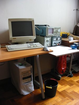
My Electronic Lab Tools & Equipments
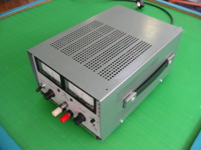
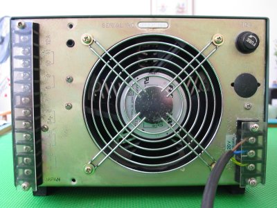
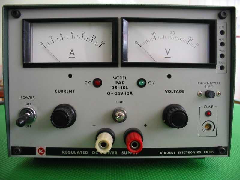
Kikusui variable DC power supply PAD 35-10L 0~35V 10A
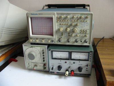
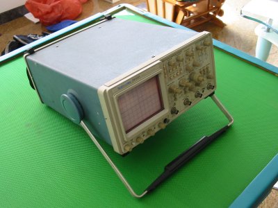
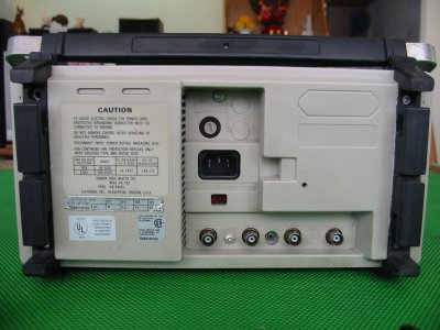
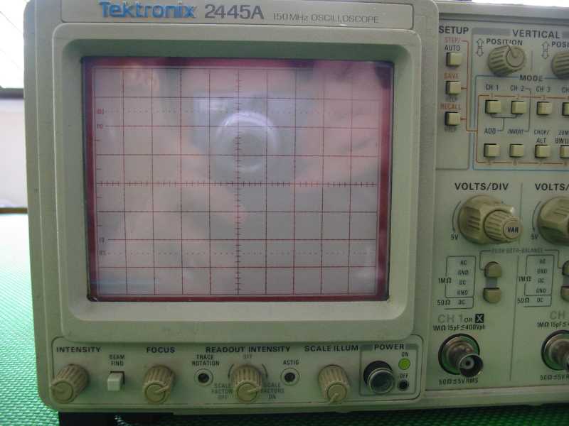
Tektronix 2445A 150Mhz Oscilloscope
Tektronix 466 100Mhz Oscilloscope
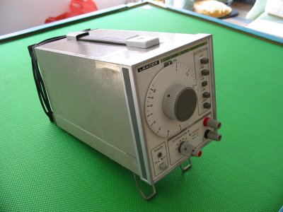
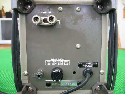
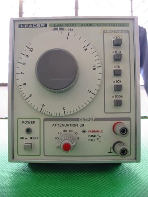
Leader LAG-120B Audio Generator
Electrical Hand Drill
Soldering Iron
My DC Variable Power
Specification
| KIKUSUI ELECTRONICS CORP Regulated DC Power Supply
|
Model: PAD 35-10L 0~35V 10A |
| Voltage range: | 0Vdc - 35Vdc |
| Current range: | 0A to 10A |
|
Function |
|
|
<1> adjustable current limit |
To limit the current up to a value. If the current drawn is greater than the value set. The power supply will seize further current supply, such that the current supplied will not exceed the limit. With some voltage adjusted, press current limit button <5>, and turn, <1> to the required current limit. |
|
<2> adjustable voltage |
Adjusting the open terminal voltage to the requirement. This also sets the voltage limit of the power supply. |
|
<3> over current indicator (C.C) |
LED lights up if current drawn is greater than the limit set. |
|
<4> over voltage indicator (C.V) |
LED lights up if voltage at the terminal is greater or equal than the voltage setting. With open terminal (not connecting any load/circuit), the C.V LED should be lighted up. When loaded, the C.V LED should be off. |
|
<5> current/Voltage limit button |
Press the button to see the current limit being set. |
|
<6> OVP function (over voltage protection) |
Adjust a limit to the voltage, such that if the system's voltage exceed the setting, the own power supply equipment will be shut down, and OVP LED will be lighted up. A reset (Off/On) will be required to reset the power supply to normal working conditions. This is a safety feature in case the voltage at the terminal is greater than expected unintentionally. |
|
<7> voltage meter zeroing |
see voltage calibration |
|
<8> current meter zeroing |
see current calibration |
|
<9> V.FS (voltage full scale) |
see voltage calibration |
|
<10> A.FS (current full scale) |
see current calibration |
|
<11> V.OS (voltage offSet) |
see voltage calibration |
|
<12> I.OS (current offset) |
see current calibration |
| <13> Voltage display | see voltage calibration |
| <14> Current display | see current calibration |
| Setting up the power supply for use: | |
| 1) Always turn current/voltage knob to minimum
(anti-clockwise) before switching on the power supply. 2) Switch ON the power supply. 3) Adjust the voltage knob to the voltage required. It is important to verify the voltage using a multi-meter. Do not rely solely on the voltage reading on the power supply equipment. 4) Press the current limit button <5>, and turn the current limit knob to the maximum current allowed. Always keep the current limit as low as possible to prevent over driving faulty circuit, which may result in burning/fire. 5) Switch OFF the power supply. 6) Connect up your circuits. 7) Switch ON the power supply. 8) If the voltage and current when switched on is not of expected, switched off the equipment and think over what is happening. |
|
| Calibrating the voltage display <13>: 1) Make sure the power supply is switch OFF. 2) Adjust the OVP <6> to maximum, to prevent the protection mode from activating. 3) Adjust the voltage knob to minimum (anti-clockwise). 4) Switch ON the power supply.. 5) Insert a digital VOLTAGE-meter and it should read 0V across the +ve -ve terminal. 6) If it does not read zero volt, adjust V.OS <11> until the digital multi-meter reads 0V. adjustment should be small and slow as the reading needs about a minute to be stable. 7) After the digital multi-meter reads 0V, it means that the output voltage at 0V has been tuned. Check the power supply voltage display 0V too. If the display does not show 0V, adjust the voltage meter zeroing <7> to 0V reading on the power supply equipment. 8) Adjust to increase the voltage to exactly 30V shown on the multi-meter. The voltage display on the power supply may not shows the 30V. Adjust V.FS <9> to adjust the voltage display to show the 30V on the equipment. Note that adjusting V.FS do not change the voltage output from the power supply equipment. 9) The equipment should be calibrated. Adjust to varies voltage to check if the voltage display tally the reading shown on your multi-meter. |
Calibrating the current reading <14>: 1) Make sure the power supply is switch OFF. 2) Adjust the voltage/current knob to minimum (anti-clockwise). 3) Insert a digital CURRENT-meter and it should read 0V across the +ve -ve terminal. Make sure the priority is correct or else your meter will be damaged. +ve probe connected to the +ve terminal, while the -ve probe to the negative. This forms a short circuit across the power supply terminal as a amp-meter is 0 ohm. 4) Switch ON the power supply. The C.C <3> indicator will light up to indicate over current. This is because the current limit knob is turn minimum, limiting the current. 5) Increase the current knob by a bit. This should turn off the C.C indicator. 6) Increase the voltage knob by a bit. The C.C indicator could be lighted up, with a current reading on the display <14>. The display reading should reads the same as your digital CURRENT-meter. Adjust to varies current limit to check if they are of the correct reading. 7) If the reading is incorrect, A.FS <10> and I.OS <12> will need to be adjusted as it is done for the voltage calibration. The procedure will be slightly more complicated as current measurement is not as direct as voltage measurement, however the priciple is still the same. Tuning the offset first followed by the meter zeroing, and lastly the full scale tuning.
|
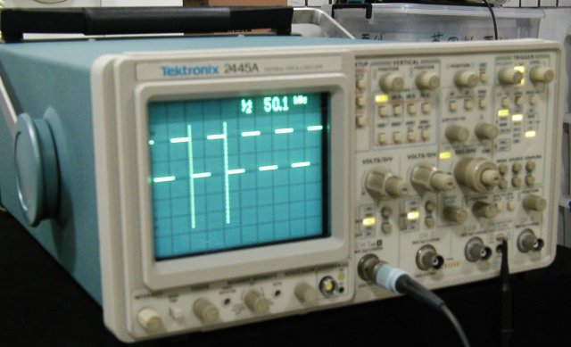
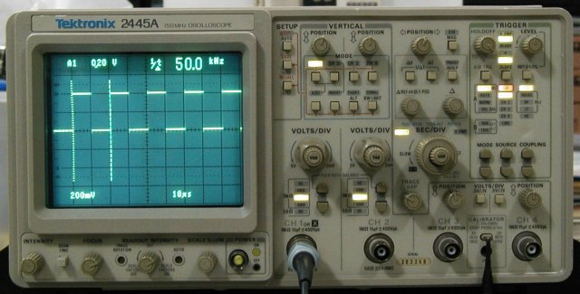
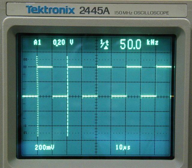
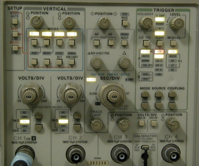
My Tektronix 2445A 150Mhz Oscilloscope
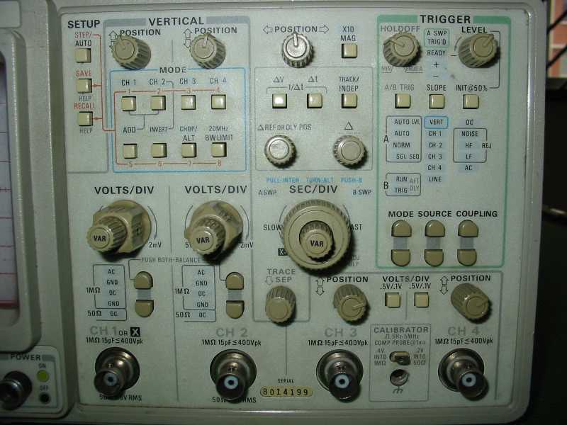
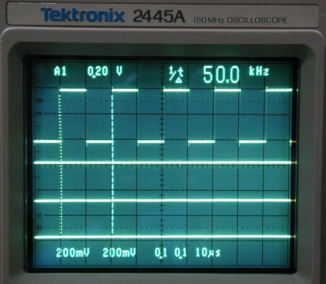
| Features | ||
| Volts measurement cursors | Specification | |
| Time measurement cursors | Form Factor | Benchtop |
| Cursor tracking | Bandwidth | 150 Mhz |
| Alphnumeric Readouts | Rise time | 2.33 ns |
| Time Measurement | Number of Channels | 4 ch |
| Voltage Measurement | Min. Vertical Sensitivity | 2 mV/div |
| CRT Readouts | Maximum Vertical Sensitivity | 5 V/div |
| Vertical(or Deflection Factor) Accuracy | 2 % | |
| Input Coupling | AC,DC,GND | |
| Input Impedance | 1 MOhm | |
| Input Impedance (alternate) | 50 Ohm | |
| Maximum Input Voltage | 400 V(dc+p) | |
| Maximum Input#2 (for Impedance #2) | 5 Vrms | |
| Main time base - lowest | 10 ns/div | |
| Main time base - highest | 1 s/div | |
| B Sweep Time Base (low) | 10 ns/div | |
| B Sweep Time Base (high) | 50 ms/div | |
| Time base Magnification factor (X?) | x10 | |
| Timebase accuracy | 0.6 % | |
| Trigger Source | External,Internal | |
| Trigger Modes | AC,Auto,DC,HF-REJ,LF-REJ,Normal,Single | |
| Display Type | Color CRT | |
| Display Size | 12.7 cm | |
| User Interface | Proprietary | |
| Out of Production |
Nov-01-2000 |
|
| CE Compliance | Not on file | |
| UL Compliance | Not compliant | |
| Power Requirements, Input Power | Universal (Auto Sense and Switch) | |
| Physical Dimensions |
Width: 330 mm Height: 190 mm Length: 434 mm Weight: 9.3 kg(20.5 lb) |
For more information regarding the use and operation of an oscilloscope, you can refer to the following document, The XYZ's of Oscilloscopes.pdf
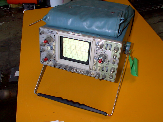
My Tektronix 466 100Mhz Analog Storage Oscilloscope
scan version of the manual for tektronix 466 oscilloscope is available in *.pdf format.


email: siongboon@yahoo.com.sg
website: Spotronics, http://www.oocities.org/sg/siongboon/