
I have always been trying construct a DC-DC circuit ever since I started using commercial DC to DC. A dc-dc is superior in terms of energy efficiency. It has the same function as a voltage regulator, eg LM7805. However it generate a lot less heat than a voltage regulator.
The input voltage must be higher then the output voltage in order for the regulator to function. The voltage is regulated and the voltage difference is dissipated through heat via the regulator package/heat sink. The higher the input voltage, the more the heat is generated.
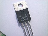
A dc-dc converter uses switching control to reduce the input dc voltage (on the average). This is equivalent to a lower input voltage resulting in minimum heat dissipated. The control results in better regulated output, less energy wasted through heat and the use for high current application. Nowadays some dc-dc converter comes in the TO-220 package.
The first one I tried using is the SD-50A-5 from Meanwell rated at 5V 10A. It is very good and easy to use. However it is too big in size. As I am doing mobile equipment, size is an important factor. This motivate me to tried out the SDM-30 from MeanWell. It is a lot smaller than the previous one, however generate lots of heat and can only handle up to 5V 5A.
I was so fortunate to meet up with a sales person, and was recommended this dc-dc PMA8811SF from Ericsson. It is by far the most compact (smaller than SDM-30) and efficient dc-dc I had seen and use. It is of surface mount package. In terms of performance, it is rated 5V 16A and generate far less heat. The down side is on the cost. It cost about S$60.
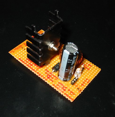
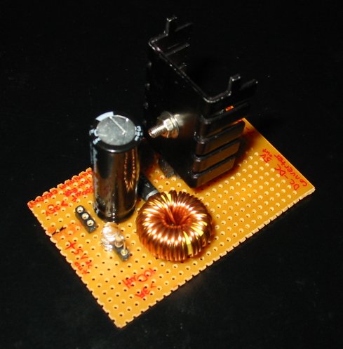
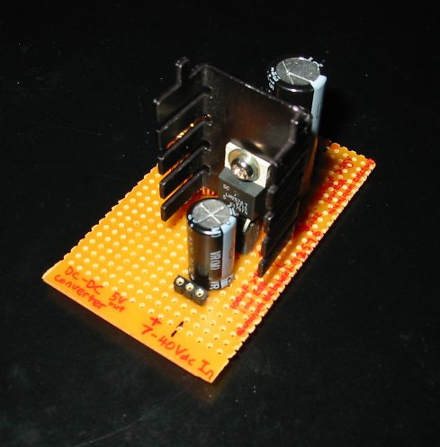
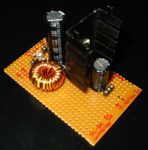
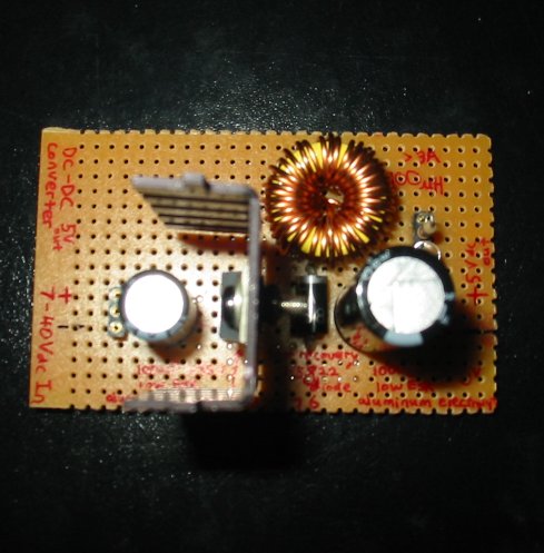
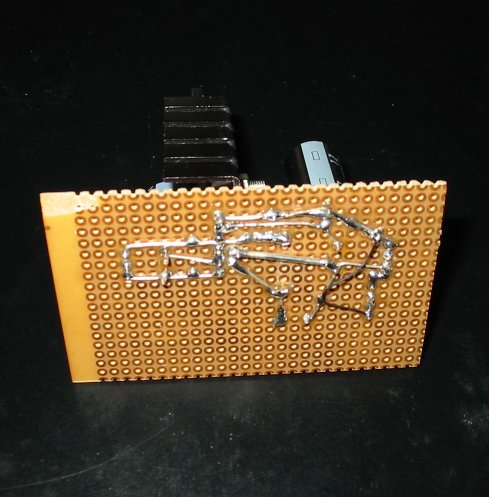
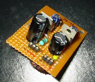
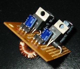
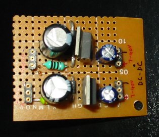
Through some research, I get to know and learn about standard dc-dc IC that do the controlling and regulating using a few external components. This motivate me to try out the LM2576 with rating up to 5V 3A. It is tough at first, because there is a component that I am not familiar with, the inductor. I have never tried doing inductor coiling at home as I lack of equipment. Fortunately, I had brought a multi-meter with inductor measurement, UT70A from Uni-Trend Technology. I brought it to replacement my old faulty digital multi-meter.
Even with a instrument to measure inductor, I couldn't kick off the project using inductor. The reason is simple. I don't know how to use it to measure inductance. The value I measured is different for each measuring range I tune to. I just couldn't understand which range to tune and couldn't read the actual measurement.
Then one day, I happen to drop by my favourite electronics shop looking for a new power supply for my home lab. I saw that they have a wide range of ready coiled inductors. Researching LM2576 at that time, I pickup the correct known inductor value, and proceed to the counter to measure using their LCR meter. To my expectation, I couldn't measure it still. I tried to approach the people there, and realised that they too do not know how to use the meter. During measurement, I realised that one of the range I tuned to is able to display the value of the known inductor. It struck my mind that I could actually use a number of known inductor's value to calibrate the meter I have at home. True enough, it works, and I am able to modified the coil inductor to my needs. This begins the journey of my dream inductor related projects, and mark the success of my LM2576 dc-dc circuits.