R/C Helicopter Hobby in Singapore
|
| Home | Why R/C Helicopter? | How to start? | Setting up | Articles | Flying Lessons | Links | Message Board | For Sale |
The Hirobo Sceadu Evo was launched in July 2003 and the initial review was excellent. Special attention was given to the new FZ-IV rotorhead, which bears ressemblance to the Minature Aircraft Fury Tempest rotorhead. It was touted to be able to perform incredible and precise 3D free style flying. Fortunately, Hirobo has sticked to it's policy of parts compatibility and hence owners of the original Sceadu are able to upgrade to the newer version with minimial changes.
Besides the new rotorhead, Evo also has a full set of push pull controls for ailerion, elevator and collective pitch. This has put the Evo on par with the bigger HiroboFreya. The use of a new mix of plastic and strengthening compound results in a much tougher plastic components. The fan is of a newer design and hopefully the infamous problem of overheating engine can be solved. The Sceadu Evo also comes with a new OS 50 Evo Spec engine. I have read that this new engine uses the OS 60B carb and this removes the issue of inconsistent running in the previous OS 50 engine.
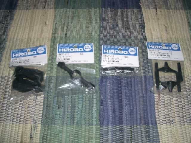
I am lucky to have a fellow flying buddy Kang getting a brand new Evo a while after it was launched. In no time, Kang's Evo was set up and flying. Wow....the precision and stability is incredible! The first time I saw the Evo flying was during a cloudy day and wind was blowing strong. Kang happily gave me a flying demostration and I saw how stable the Evo sit in hover in cross wind condition. I have flown the original Sceadu and also help my flying buddy William set up his Freya. I can only say that the Evo is much better than the Sceadu and is almost on par with the Freya in terms of hovering stability. Next, Kang showed me some circuit flying, loops and rolls. But the impression was already made and I decided to upgrade my FZ-III rotorhead to the new FZ-IV rotorhead. Quickly an order to Cyberheli was made. The FZ-IV has the following parts that are different from the FZ-III. They are the seesaw, blade grips, mixing arm and stabiliser control arm.
From left to right: 0412-211 FZ-IV blade grips, 0412-212 FZ-IV seesaw, 0412-213 FZ-IV mixing arm and 0412-214 FZ-IV stabiliser control arm. These four items cost around S$50.
For no apparent reason, I started the process by changing the seesaw first. The original seesaw assembly has 4 bearings. I am happy that these bearings fit the newer seesaw. It is good that two spacers are included for use on the screws that do into the main mast. New bushings are also provided. In the original seesaw, I have to file down the bushings to remove slope. I prefer a slope free rotorhead, partly due to influence from my flying buddying Kian Lim. But with the new bushings and spacer, the is no slope at all. The newer FZ-IV seesaw is much larger than the FZ-III seesaw.

The FZ-IV seesaw is supplied with new bushings, spacers and hex screw.
I installed the seesaw according to the manual. Please note that the "Hirobo" logo should be facing up.

The FZ-IV seesaw installed. Noe that you can reuse the bearings from the FZ-III seesaw.
After installing the seesaw, I proceed onto the mixing arms. This is very special. The original FZ-III mixing arm controls only the blade pitch. But on the new FZ-IV mixing arm, an elevator or ailerion input will give a slight change in the blade pitch! It's kind of unusual, and I expect that in flying, any cyclics input might result in a "twitch" in the blade pitch and hence, causing the heli to change height suddenly. However, I saw how the Evo flies and this is not true! I think I can only figure it out once I do the first flight.
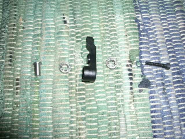
The FZ-IV mixing arm, also provided in the package are new bushings, spacers and hex screw. The bearings are taken from the FZ-III mixing arm.
The FZ-IV mixing arm can be secured to the seesaw at 2 positions. According to the manual, it is suggested that the inner hole is for high mobility, which I presume to be 3D freestyle flying. The outer hole is for autostability and I assume that is for F3C type of flying. I have read on RunRyder that many people prefer to use the outer hole. But I like to find out how "mobile" it is and I fix the mixing arm to the inner hole. Note that on the mxing arm, the inner ball connects to the blade pitch linkage rod and the outer ball connects to the mixing arm linkage rod. However, after assembly, I found that the outer ball rubs against the seesaw slightly. It may be alright when the rotorhead is spinning, because centrifudge force will push out the mixing arm. But I'm paranoid and decide to tighten down the ball screw and file a tiny bit off the screw head.
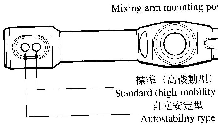
Diagram showing mixing arm mounting position. Taken from the Evo manual.
The next item is the FZ-IV stabiliser control arm. The FZ-IV stabiliser control arm is very much bigger than the older FZ-III. The assembly method is very much similar to the method use for the FZ-III stabiliser arm. The package includes new flybar metal holders, balls and hex screw. Note that the "Hirobo" logo should be facing up. Please be careful with screwing. The new plastic is hard and you have to use strength to screw the hex screw into the plastic. But too much strength will strip the threads. Make sure that the hex screw that holds the ball in between the control arm has to be tight, or else the control arm will flex. Next, fix the control arm and insert the flybar. Make sure that the length on either side is the same and align the paddles. Use locktight to hold down the grub screws.

The FZ-IV stabiliser control arm package includes new ballds, hex screws, grub screws and metal flybar holder.
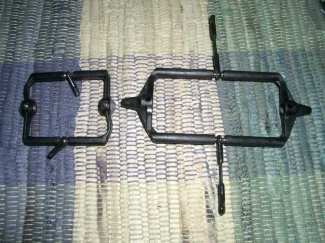
Comparing the FZ-III stabiliser control arm(left) and FZ-IV stabiliser control arm(right).

The completed upper portion of the FZ-IV rotorhead. The remaining parts at the lower portion are the same.
The last item from the FZ-IV rotorhead is the blade grip. It looks almost the same as the FZ-III, except that there is two ball position on the leading edge of the blade grip. Use the outer hole as recommended by the manual. You can reuse the original bearings. Please take care on assembling the series of normal and thrust bearings. Use generous amount of grease on the thrust bearings. Also note that there is an "larger inner diameter" spacer and "smaller inner" spacer that sandwhich the thrust bearing. The "larger inner diameter" spacer can slide onto the spindle easier while the "smaller inner diameter" spacer doesn't slide easily.
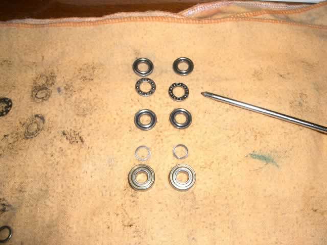
The sequence of bearings that go into the blade grip.
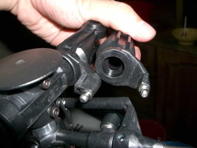
Comparing the FZ-IV blade grip and FZ-III blade grip. Note that I use the outer hole.
Finally, reassemble the whole rotorhead. Stupid me, I broke the plastic anti rotation guide. Well, I guess I have to get the metal one for replacement. My policy is not to get "shiny" parts, unless the old one is spoilt.
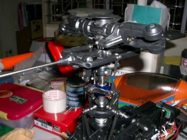
The completed FZ-IV rotorhead, minus the linkage rod.
I have not yet set up the linkage rod length. But my initial guess is that only some of the rod can be reuse. I may have to get new ones. I will post another article on setting up the FZ-IV rotorhead once I get the linakge rods done.