R/C Helicopter Hobby in Singapore
|
| Home | Why R/C Helicopter? | How to start? | Setting up | Articles | Flying Lessons | Links | Message Board | For Sale |
contributed by Clarence Boudville
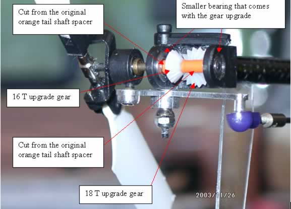
Tail gearbox free play reduction
This modification will help reduce the free play of the tail
rotor shaft and subsequent tail control as a result of the modified speed up
upgrade gear set.
Items required:-
The stock orange tail shaft spacer.
Step 1:- Test fit the upgrade (white) gear (i.e. smaller one, 16T) on the tail
rotor shaft with the bearings (smaller ones) fitted into the gear box. Measure
the gap between the gear and the gearbox body when the small gear meshes with
the drive gear (bigger one 18T).
Step 2:- Now cut the orange tail shaft spacer to about ? mm longer than the measured gap. (You will need this to accommodate the compression forces when you reinstall the shaft to the gear later).
Step 3:- Now test fit the gear with the cut spacer and check the gear meshing. Now Measure the other side of the gear to the gear box and then cut the remaining orange spacer to about 1/2mm longer. Now install this spacer and continue to push the tail rotor shaft all the way in until it rest on the other small bearing.
Step 4:- Adjust the meshing of the main tail drive gear and
tighten the tail gear box grub screw on to the tail boom.
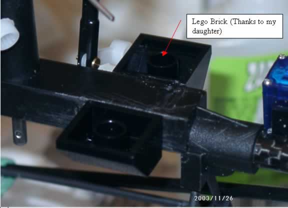
LEGO CCPM Servo Mount
This modification will allow a very straight CCPM linkage arrangement while having a very secure servo mount.
Items required:-
Lego beveled brick.
Cable tie
Step 1:- Shave off the protrusions of the Lego brick (so that it does not look like a Lego brick….he! he!).
Step 2:- Line up the Aileron and Pitch servos and than adjust the brick to get the most vertical linkage arrangement.
Step 3:- CA or Epoxy the Lego brick in place and then secure the servos with a cable tie.
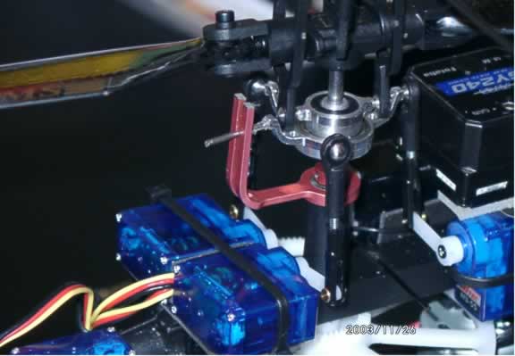
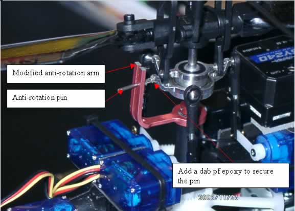
Anti-rotation Arm Modification
This is required to ensure the main blade does not strike the upgraded metal anti-rotation arm during hard 3D maneuvers.
Step 1:- With the main blade and rotor head & servos installed, put to full negative pitch with forward elevator and see where the swash plate anti-rotation pin lines up on the anti-rotation arm. Mark about 3 mm above where the pin lines up. Now also tilt the main rotor back to a position just before boom strike and check the marking on the anti-rotation arm.
Step 2. Dismantle the anti-rotation arm and then cut it with a Dremel cutting tool and reinstall. Also add a dab of epoxy on the anti rotation pin where it fits the swash plate to add further security.